In the realm of automotive mechanics, the alternator stands as a pivotal component, often underestimated yet indispensable for the seamless operation of your vehicle. This article delves deep into the workings of a car alternator, a critical part of your car’s electrical charging system. We will explore its intricate parts and elucidate how they collaborate to power your car’s electrical systems and keep your battery charged.
Understanding the Role of a Car Alternator
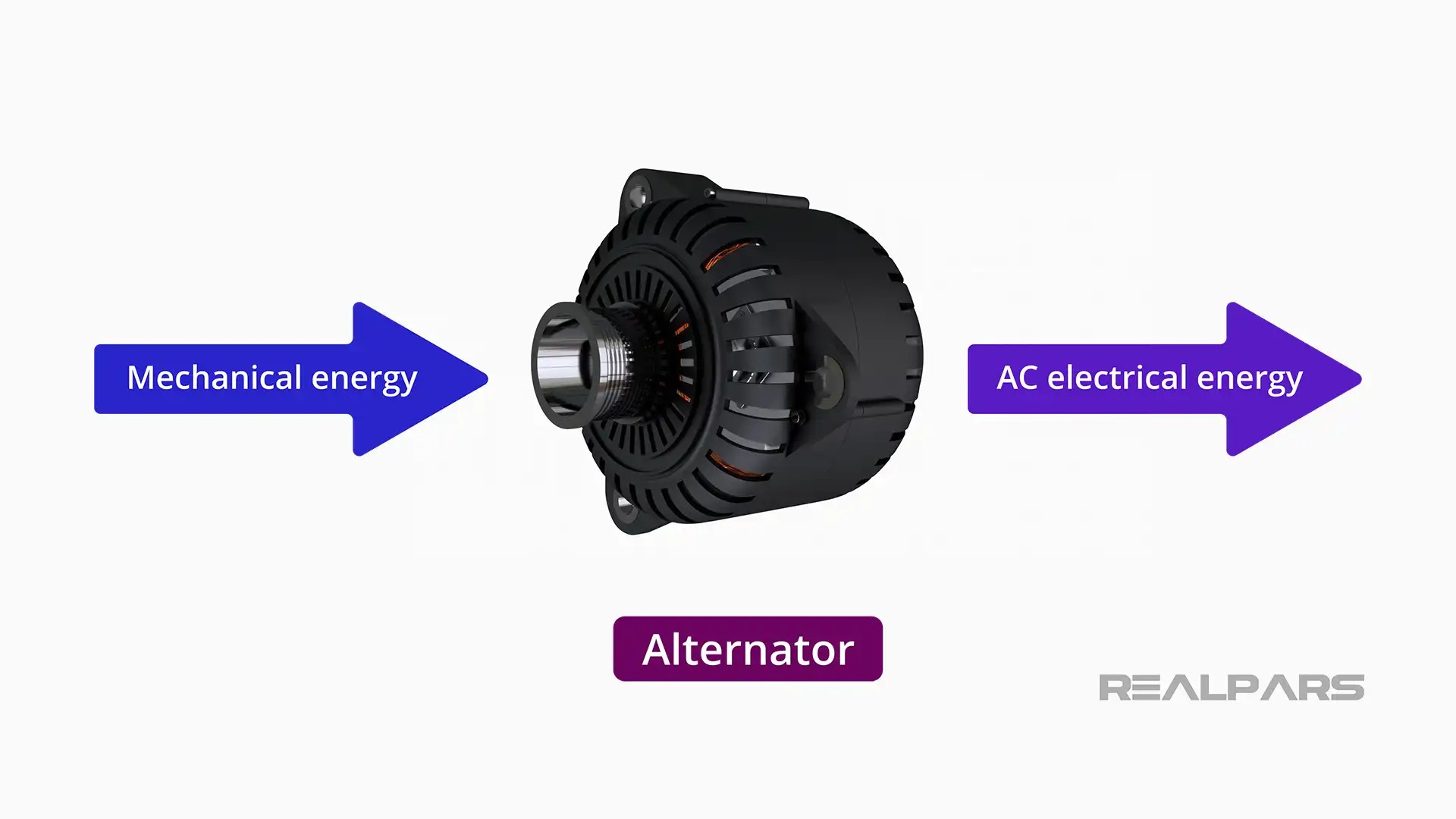
Let’s start with the fundamentals. What exactly is a car alternator, and what is its primary function? An alternator is fundamentally an electromechanical device that converts mechanical energy from the engine into alternating current (AC) electrical energy.
In a car, the engine’s rotational force is harnessed via a drive belt to spin a pulley connected to the alternator. Although cars operate on direct current (DC) voltage, the alternator initially generates AC, which is then converted to DC. The primary role of the alternator is to generate power while the engine is running. This generated power serves two crucial purposes: charging the car battery and supplying electricity to operate the vehicle’s electrical systems. The battery is primarily responsible for providing the high current needed to start the engine. Once the engine is running, the alternator takes over, ensuring continuous power for all electrical components and recharging the battery.
Alternator vs. Generator: Key Differences
Often, the terms “alternator” and “generator” are used interchangeably, but there’s a technical distinction. As we defined, an alternator converts mechanical energy to AC electrical energy. A generator, in broader terms, is a mechanical device that converts mechanical energy into either AC or DC electrical energy.
Therefore, in a strict sense, an alternator can be classified as a type of generator, specifically one that produces alternating current. However, in automotive contexts, “alternator” is the universally accepted term for the charging device in modern vehicles due to its specific design and functionality.
Major Components of a Car Alternator
Car alternators, while varying in construction details across manufacturers, generally consist of three primary components: the rotor, the stator, and the rectifier. Beyond these, there are other essential parts that we will explore to fully understand how an alternator functions.
1. The Rotor: The Rotating Electromagnet
The rotor is the rotating heart of the alternator. Driven by the engine via a drive belt and pulley system, the rotor spins on a shaft at high speeds when the engine is running.
At its core, the rotor is an electromagnet. This electromagnet is formed by field windings – a coil of conductive wire wrapped around a magnetic metal core. When voltage is applied to this wire coil, it generates a current, which in turn creates a magnetic field around the coil. This magnetic field behaves much like a permanent magnet, possessing both a North and South pole.
To enhance the magnetic field interaction, the rotor also incorporates finger pole pieces. These are a series of alternating North and South poles strategically positioned around the field windings, further concentrating and directing the magnetic field as the rotor spins.
2. The Stator: Generating AC Voltage
The stator is the stationary counterpart to the rotor, positioned encasing the rotor. The rotor spins freely inside the stator without any physical contact. The stator is where the electrical power generation actually happens.
The stator is composed of three separate coil windings. These windings are interconnected at one end, and they are strategically positioned at 120-degree intervals around the stator’s iron core. This specific arrangement is crucial for generating three-phase AC power.
The precise 120-degree spacing of the stator coil windings ensures a balanced three-phase AC output.
The magic of voltage generation within the stator relies on Faraday’s Law of Induction. This principle, discovered by Michael Faraday, states that a voltage is induced in a coil of wire when it moves through a magnetic field, or when a changing magnetic field passes through a stationary coil.
In the alternator, the rotor’s spinning electromagnet creates a rotating magnetic field. As this magnetic field sweeps across the stationary stator windings, it induces a voltage in each coil. The faster the rotor spins (and thus, the faster the magnetic field changes), the greater the induced voltage.
This process results in the generation of three AC voltages across the stator windings, due to the rotating magnetic field from the rotor.
Brushes and Slip Rings: Powering the Rotor
To create the crucial magnetic field in the rotor, we need to supply voltage to its field windings. This is where brushes and slip rings come into play.
Slip rings are conductive rings mounted on the rotor shaft, and brushes are stationary contacts that ride against these slip rings. Voltage is applied to the rotor’s field winding through these brushes and slip rings. This arrangement allows for continuous electrical connection to the rotating rotor.
The voltage supplied to the rotor initially comes from the car battery when the ignition is turned on. Once the alternator starts generating its own power, a portion of this output is used to energize the rotor’s electromagnet, creating a self-sustaining cycle.
With the electromagnet rotor spinning inside the stator, three AC voltages are induced in the stator windings. These AC voltages are phase-shifted by 120 degrees due to the physical arrangement of the windings. However, cars require DC voltage. This is where the rectifier comes into play.
3. The Rectifier: Converting AC to DC
The rectifier’s job is to convert the generated AC voltage from the stator into DC voltage, which is necessary to charge the car battery and power the vehicle’s DC electrical systems. A rectifier utilizes diodes to achieve this conversion.
A diode is a semiconductor device that acts as a one-way valve for electrical current, allowing current to flow in only one direction. It has two terminals: the anode and the cathode. Current flows from the anode to the cathode only when the anode is more positive than the cathode.
When an AC voltage is applied to a diode circuit, the diode blocks the negative half-cycles of the AC waveform. This process, known as rectification, results in a pulsating DC voltage. While not smooth DC, it’s a step towards converting AC to DC.
Car alternator rectifiers typically employ six diodes. These diodes are often mounted on a heat sink to dissipate heat generated during operation and protect them from thermal damage.
The use of six diodes in a full-wave rectifier configuration allows for rectification of both positive and negative half-cycles of all three AC voltages generated by the stator windings. This results in a more efficient and smoother DC output compared to using just one or two diodes.
Diode Trio: Self-Excitation for Continuous Operation
Earlier, we mentioned that the rotor needs voltage to create its magnetic field. While initially supplied by the battery, once the alternator is running, it becomes self-excited, meaning it uses a portion of its own output to power the rotor. This self-excitation is facilitated by the diode trio.
A diode trio is a module containing three diodes. Similar to the main rectifier, the diode trio’s input terminals are connected to the stator voltage outputs. The outputs of these diodes are connected together, rectifying a portion of the stator’s AC output into DC voltage. This DC voltage from the diode trio is then used to energize the rotor’s field winding, maintaining the magnetic field necessary for continued power generation.
Voltage Regulator: Maintaining Stable Voltage
The voltage regulator is a critical electronic component that ensures the alternator output voltage remains stable and within safe limits, protecting the car’s electrical system and battery.
Voltage regulators come in various designs and forms, depending on the alternator model and manufacturer.
The regulator acts as an “alternator voltage monitor.” It continuously senses the battery voltage and adjusts the current supplied to the rotor’s field winding. If the battery voltage is low, the regulator increases the rotor field current, strengthening the magnetic field and increasing stator output voltage. Conversely, if the battery voltage is too high, it reduces the rotor field current, decreasing the output voltage. This feedback loop maintains a relatively constant output voltage despite variations in engine speed and electrical load.
Maintaining a stable alternator voltage is crucial to prevent overcharging the battery and damaging sensitive electronic components in the vehicle.
How All Alternator Parts Work in Harmony
Let’s summarize how all these components work together to generate power and charge your car battery:
- Ignition Start: When you turn the ignition key, battery voltage is supplied to the rotor field winding through the brushes and slip rings, initiating the magnetic field.
- Engine Start & Rotor Rotation: The engine starts, and the drive belt spins the alternator rotor.
- Stator Voltage Generation: As the rotor spins within the stator, AC voltages are induced in the stator windings.
- Rectification to DC: The rectifier converts the AC voltage from the stator to DC voltage.
- Voltage Regulation: The voltage regulator monitors the battery voltage.
- Output to Battery & Electrical Systems: The rectified DC voltage is supplied to charge the battery and power the vehicle’s electrical systems.
- Feedback Loop: If the voltage is too high, the regulator reduces rotor field current; if too low, it increases field current, maintaining a stable output.
- Self-Excitation: The diode trio provides DC voltage to the rotor field winding, enabling the alternator to become self-sustaining once the engine is running.
It’s important to remember that alternator designs can vary slightly across manufacturers and models. The diagrams and explanations here provide a general understanding of the common principles and components found in most car alternators.
Summary of Car Alternator Function
Let’s recap the key takeaways about how a car alternator works:
- A car alternator is an essential electromechanical device that generates DC voltage to charge the battery and power the vehicle’s electrical systems while the engine is running.
- The main components include the rotor (electromagnet), stator (AC voltage generator), rectifier (AC to DC converter), diode trio (self-excitation), and voltage regulator (voltage stabilization).
- The rotor spins inside the stator, inducing three-phase AC voltages in the stator windings.
- The rectifier converts these AC voltages into DC voltage.
- The voltage regulator ensures a constant output voltage, protecting the battery and electrical components.
- The diode trio enables the alternator to self-energize and maintain operation once the engine is started.
If you have further questions about alternators, car electrical systems, or any other automotive electrical topics, please feel free to leave a comment below. We are committed to responding within 24 hours. If you found this article informative, please share it with friends, clients, or colleagues who might benefit from this knowledge.