Electrical problems in your car can be frustrating. From faulty terminals to broken wires, blown fuses, and failing relays, diagnosing these issues can be the key to getting back on the road quickly. Understanding How To Check Car Relays is a valuable skill that can save you time and money.
Modern vehicles are increasingly complex, relying heavily on electrical systems and computerization. Many components that require high electrical currents utilize relays to control circuits. Because relays contain moving parts, they are susceptible to wear and tear over time and can eventually fail. When a relay malfunctions, it can be difficult to pinpoint the problem.
Fortunately, cars.edu.vn is here to guide you through the process of testing these small but crucial electronic switches.
Safety Precautions When Working With Car Electricals
Working on your car involves inherent risks. Moving parts like fans and belts, and electrical components can cause injury if precautions aren’t taken. Always prioritize safety when working on your vehicle, especially when dealing with electrical systems.
Here are essential safety tips to keep in mind:
- Electricity is dangerous. Always exercise caution when working with electrical components in your car.
- Avoid flammable environments. Sparks from electrical work can ignite flammable liquids or gases. Ensure your workspace is well-ventilated and free of such hazards.
- Consult reliable resources. Refer to your vehicle’s official safety manual and a reputable repair manual for specific instructions and safety guidelines. While this guide offers helpful tips, manufacturer resources are authoritative for both technical procedures and safety advice.
Tools and Equipment for Testing Car Relays
Testing a car relay is a straightforward process you can perform at home with minimal tools. While you can use your car’s battery and a multimeter in a pinch, a benchtop power supply setup provides a more controlled testing environment. Here’s a list of everything you’ll need to effectively test a car relay:
Tools and Parts List:
- Multimeter: Essential for measuring voltage, resistance (ohms), and continuity. A digital multimeter is recommended for ease of use and accuracy.
- Power Supply (Benchtop or 9V/12V Battery): A benchtop power supply offers adjustable voltage for precise testing. Alternatively, a 9-volt or 12-volt battery can be used to energize the relay coil.
- Jumper Wires or Alligator Clips: For connecting the power supply or battery to the relay pins and multimeter probes.
- Relay Specification Sheet (Optional): If available, the relay’s datasheet can provide specific resistance values for the coil, aiding in accurate testing.
Step-by-Step Guide: How to Test a Car Relay
Step 1: Understanding the Relay’s Function
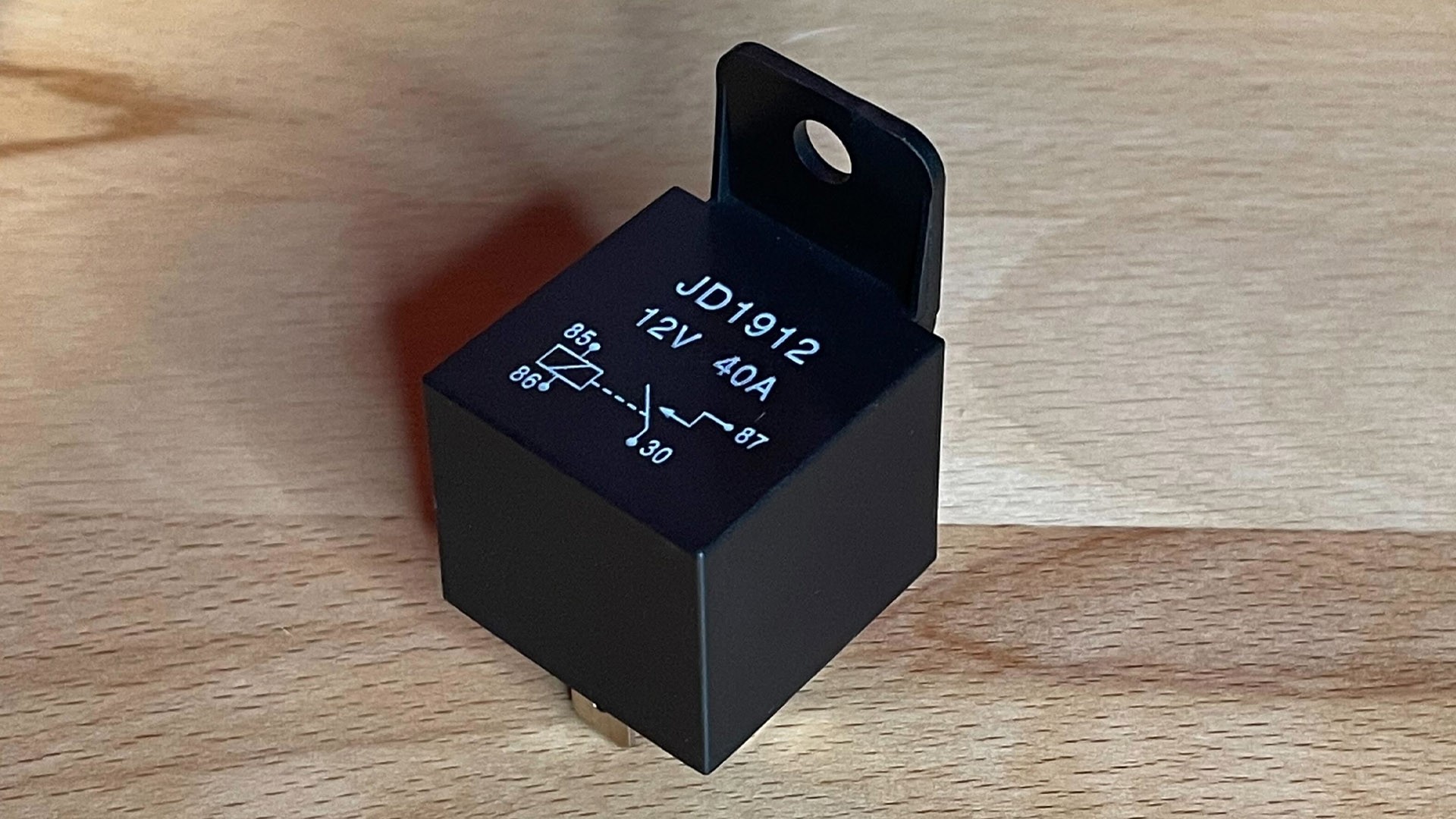
Before testing, it’s crucial to understand how a relay operates. While various relay types exist, this guide focuses on the common four-pin Single-Pole Single-Throw (SPST) normally open relay found in many vehicles.
These relays typically have four pins labeled 85, 86, 87, and 30. Pins 85 and 86, usually positioned opposite each other, connect to the electromagnetic coil circuit. Pins 87 and 30 are part of the switched circuit. When the electromagnetic coil circuit is energized, it magnetically closes a switch between pins 87 and 30, allowing current to flow through the relay and power the connected component (like headlights or a cooling fan).
The DIN 72552 standard formally defines these pin designations:
- 30: Power input from the battery positive terminal (+)
- 85: Relay coil ground (-)
- 86: Relay coil positive (+)
- 87: Common output contact (Normally Open – NO)
- 87a: Normally closed contact (NC – not present on typical 4-pin relays)
- 87b: Normally open contact (NO – typically pin 87 on 4-pin relays)
Step 2: Locating the Relay in Your Vehicle
Once you’ve determined that you need to test a specific relay, the next step is to locate it in your car. Relay locations can vary depending on the vehicle make, model, and the system the relay controls. Relays can be found in various locations: under the hood in the engine bay, within fuse boxes (both under the hood and inside the cabin), under the dashboard, or even in less obvious spots.
Consult your vehicle-specific repair manual or wiring diagrams to pinpoint the exact location of the relay you need to test. These resources will provide the most accurate information for your car.
Step 3: Relay Swapping for a Quick Check
The simplest initial test for a suspect relay is to swap it with a known-good relay of the same type. Often, identical relays are used for different, non-essential vehicle functions (like windshield wipers or rear defogger). If the problem disappears after swapping, the original relay is likely faulty.
However, be cautious: if the initial relay failed due to an underlying issue in the circuit (like a short circuit or excessive current draw), swapping in a new relay without fixing the root cause could damage the new relay as well. Relay swapping is a quick diagnostic step, not a permanent fix.
Step 4: Measuring Coil Resistance with a Multimeter
Now it’s time to use your multimeter for more precise testing. You can test the relay while it’s still in the car, or remove it for bench testing as shown. Regardless, ensure the relay is de-energized (power removed) before proceeding.
Set your multimeter to measure resistance (Ohms – Ω). To check the relay coil, you’ll measure resistance across the coil pins, which are pins 85 and 86 on a typical four or five-pin relay.
A healthy relay coil should typically show a resistance value between 50 and 120 ohms. Values outside this range indicate a problem with the coil winding, meaning the relay needs replacement. An open circuit (infinite resistance) or very low resistance (close to zero) both suggest a faulty coil.
Step 5: Testing Switch Pin Continuity (Normally Open State)
After verifying the coil’s integrity, the next step is to test the switch pins. In a normally open (NO) relay, the switch pins (typically 87 and 30 on a four-pin relay) should have no continuity when the relay is at rest (not energized). This means the circuit is open, and no current should flow between these pins in the default state.
Keep your multimeter set to measure resistance (Ohms). Place the multimeter probes across the switch pins (87 and 30). You should read infinite resistance or “OL” (over limit) on the multimeter display, indicating no continuity. If you measure continuity (close to zero ohms), it means the switch contacts are stuck closed, and the relay is defective.
Step 6: Testing the Energized Relay (Continuity Test)
Having confirmed the relay’s passive state, it’s time to test its operation when energized. Use a benchtop power supply, a 9V battery, or your car’s 12V system to energize the relay coil. Connect the power source to the coil pins (85 and 86 – polarity may matter, check relay specs if unsure, but often pin 86 is positive and 85 is ground).
Upon energizing the coil, you should hear a distinct “click” sound from the relay. This click indicates that the electromagnetic coil is working and the internal switch is mechanically closing.
Now, switch your multimeter to the continuity setting. This setting often emits an audible beep when a circuit is complete, which is helpful when focusing on the relay during testing. Place the multimeter probes across the switch pins (87 and 30). With the relay energized, the switch should now be closed, and you should hear a beep from the multimeter, indicating continuity between the switch pins.
If you don’t hear a click when energizing the coil, or if you don’t get a continuity beep across the switch pins when energized, the relay is faulty and needs to be replaced.
Step 7: Voltage Drop Test (Energized Relay)
Even if the relay switches and shows continuity when energized, it’s still important to check for potential voltage drop across the relay contacts. Corroded or worn internal contacts can restrict current flow, leading to reduced voltage at the component being powered.
Set your multimeter to measure DC Volts. Ensure you know the voltage of your power supply source (e.g., 12V from car battery or bench supply). With the relay energized and power applied to pin 30 (input side of the switch), measure the voltage at pin 87 (output side of the switch) without any load connected.
The voltage reading at pin 87 should be very close to the source voltage. A significant voltage drop (e.g., more than 0.5V difference) indicates excessive resistance within the relay contacts. In such cases, even if the relay seems to switch, it should be replaced to ensure proper circuit operation and prevent performance issues for the component it controls.
Congratulations! You’ve successfully tested your car relay. By following these steps, you can confidently diagnose relay problems and ensure your vehicle’s electrical systems are functioning correctly.
Video Tutorial: How to Test a Car Relay
For a visual demonstration of the relay testing process, consider watching a video tutorial. Seeing the steps performed can be a valuable supplement to this written guide, especially if you are new to electrical testing. Numerous helpful videos are available online that can further clarify the process of measuring a four-pin relay.
Get Equipped with Quality Tools
Our team at cars.edu.vn rigorously tests a wide range of automotive tools, parts, and equipment. Rely on our expertise and hands-on evaluations to guide you in selecting the best gear for your DIY automotive projects and maintenance tasks.
SEE GIFT GUIDES