Modern vehicles are increasingly reliant on complex electrical systems, and with age, various electrical issues can arise. From corroded terminals and damaged wires to blown fuses and faulty relays, diagnosing these problems is crucial for any car owner. Understanding how to pinpoint the source of electrical gremlins can save you from roadside frustration and empower you to perform effective repairs.
Relays, acting as electrically operated switches, are essential components in many automotive circuits, especially for high-current applications. These small devices control larger currents using a smaller electrical signal, protecting sensitive circuits and switches. However, due to their moving parts and constant operation, relays can fail over time, leading to perplexing electrical problems. If your car is experiencing electrical issues such as non-functional lights, fuel pumps, or horns, a faulty relay could be the culprit.
Fortunately, testing a relay is a straightforward process that can be performed at home with basic tools. Cars.edu.vn is here to guide you through each step, providing you with the knowledge and confidence to test your car’s relays and troubleshoot electrical problems effectively. Let’s dive into how to test a relay on your car and get your vehicle back in top shape.
Essential Safety Precautions
Before you begin any work on your vehicle, especially electrical systems, safety should always be your top priority. Automotive electrical systems can be dangerous, and it’s essential to take proper precautions to prevent injury.
Here are crucial safety tips to keep in mind:
- Electricity is dangerous: Always be aware of the potential for electric shock. Disconnect the car battery when possible and avoid working with electrical components in wet conditions.
- Flammable materials: Never work around flammable liquids or gases while dealing with electrical systems. Sparks from electrical work can ignite combustible materials.
- Consult manuals: Always refer to your vehicle’s official safety manual and a reputable repair manual specific to your car model. These resources provide detailed safety instructions and procedures relevant to your vehicle. While this guide offers helpful tips, always prioritize official documentation for technical accuracy and safety guidelines.
Tools and Equipment for Testing Relays
Testing a relay is a simple task that requires minimal equipment. While you can perform a basic test using just your car’s battery and a multimeter, a more controlled bench test setup with a power supply is ideal for thorough diagnostics. Here’s a list of the tools and parts you’ll need:
Tools and Parts:
- Multimeter: A multimeter is indispensable for electrical testing. You’ll use it to measure resistance, continuity, and voltage.
- Power Supply (Benchtop Recommended): A benchtop power supply provides a stable and adjustable power source for testing relays outside of the car. Alternatively, you can use your car battery in a pinch.
- Jumper Wires: Jumper wires with alligator clips are helpful for connecting the relay to the power supply and multimeter.
- Vehicle-Specific Repair Manual or Wiring Diagram: Knowing the location of relays and understanding your vehicle’s wiring diagram is crucial. Consult your repair manual for this information.
Step-by-Step Guide: How to Test a Relay
Now, let’s walk through the process of testing a relay, step by step.
Step 1: Understanding Relay Functionality
Before testing, it’s important to understand how a relay operates. While various types of relays exist, we’ll focus on the common four-pin Single-Pole Single-Throw (SPST) normally open relay, widely used in automotive applications.
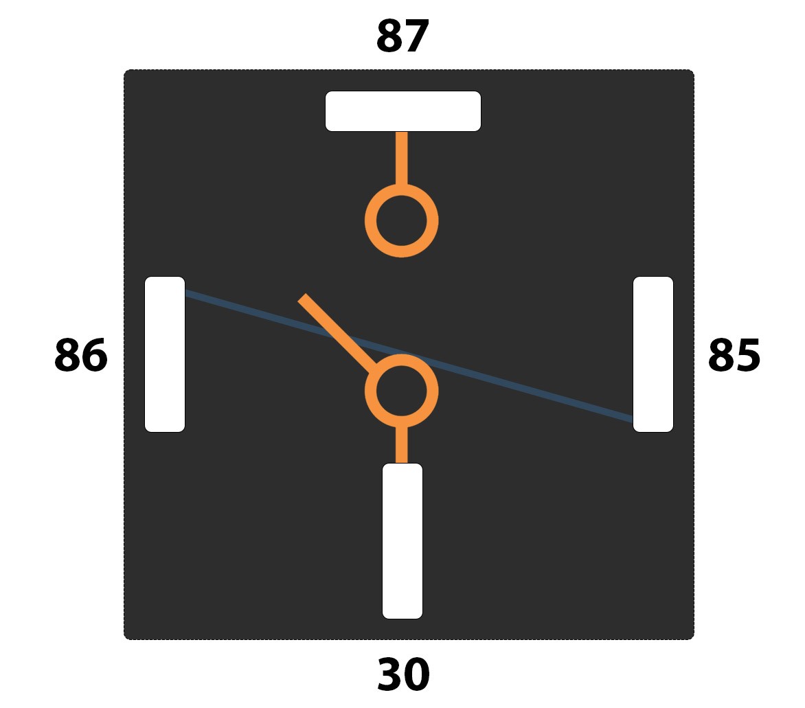
These relays typically have four pins labeled 85, 86, 87, and 30. Pins 85 and 86 are for the electromagnetic coil circuit, while pins 87 and 30 are for the switched circuit. When the electromagnetic coil circuit (pins 85 and 86) is energized with a small current, it creates a magnetic field that pulls a switch closed. This closed switch then connects pins 87 and 30, allowing a larger current to flow through the relay and power the connected component, such as headlights or a cooling fan. When the power to the coil is removed, the switch opens, interrupting the circuit between pins 87 and 30 and stopping the flow of current.
The DIN 72552 standard defines these pin numbers as follows:
- 30: Power input from the battery (+)
- 85: Relay coil ground (-)
- 86: Relay coil power (+)
- 87: Switched output contact (Normally Open)
- 87a: Normally Closed Contact (Not present in SPST relays, but in SPDT)
- 87b: Normally Open Contact (Second Normally Open contact in some relays)
For our guide, we will focus on testing the standard pins 30, 85, 86, and 87 of a typical 4-pin relay.
Step 2: Locating the Relay in Your Vehicle
The first practical step is to locate the relay you suspect is faulty. Relay locations vary significantly depending on the vehicle’s make, model, and the system the relay controls. Relays can be found in several locations:
- Under the Hood: Often housed in the main fuse and relay box in the engine compartment.
- Dashboard Area: Relay boxes can also be located under the dashboard, often behind the glove compartment or lower dash panels.
- Specific Locations: Some relays might be positioned closer to the component they control.
The most reliable way to find a specific relay is to consult your vehicle’s repair manual or wiring diagrams. These resources will provide accurate locations and diagrams of your vehicle’s electrical system, including relay positions. Many fuse boxes also have diagrams printed on the inside of their covers, indicating the location and function of each relay and fuse.
Step 3: The Swap Test (Quick Check)
One of the quickest ways to check a suspect relay is to swap it with a known-good relay of the same type. Relays are often interchangeable within the same vehicle if they have the same pin configuration and rating.
If you suspect a specific relay is faulty, identify another relay in your vehicle that is identical and controls a less critical system – for example, swapping a headlight relay with a rear window defogger relay (if they are the same type). Carefully remove both relays and swap their positions.
If the problem you were experiencing resolves after the swap, and the function controlled by the swapped-in relay now malfunctions, it’s highly likely the original relay is faulty. However, be cautious: if the original problem caused the first relay to fail, it could also damage the replacement if the root cause is not addressed. This swap test is a quick diagnostic step, not a permanent solution.
Step 4: Resistance Testing of the Relay Coil
For a more definitive test, use your multimeter to check the relay’s internal components. Start by testing the relay coil’s resistance. This confirms the coil is intact and within the expected operating range.
Set your multimeter to measure resistance (Ohms – Ω). On a four or five-pin relay, the coil terminals are typically pins 85 and 86. Place the multimeter probes on pins 85 and 86.
A healthy relay coil should show a resistance reading within a specific range, typically between 50 and 120 ohms. This range can vary slightly depending on the relay type, so consulting the relay’s specifications, if available, is ideal. A reading significantly outside this range (too high or zero/very low) indicates a faulty coil, meaning the relay needs replacement. Infinite resistance (open circuit) means the coil is broken, while very low resistance (short circuit) means the coil is internally damaged.
Step 5: Continuity Test of the Switch Pins (Normally Open State)
Next, test the switch contacts in their normally open (unenergized) state. In a normally open relay, there should be no continuity between the switch pins (30 and 87) when the relay is not powered.
Keep your multimeter in resistance (Ohms) mode. Place the probes on the switch pins, typically 30 and 87 on a four-pin relay.
In the normally open state, the multimeter should display infinite resistance or “OL” (Over Limit), indicating no continuity. If you measure continuity (close to zero ohms), it means the switch contacts are stuck closed, and the relay is faulty. A normally open relay should only show continuity between pins 30 and 87 when energized.
Step 6: Testing the Relay in Energized State (Continuity)
Now, we need to test the relay’s switching action when it’s energized. This verifies that the relay can properly close the switch contacts when power is applied to the coil.
You’ll need a power source to energize the relay coil. A benchtop power supply set to the relay’s operating voltage (usually 12V for automotive relays) is ideal. Alternatively, you can carefully use a 9V battery or your car’s 12V system.
Connect the positive terminal of your power supply to pin 86 and the negative terminal to pin 85 of the relay. When you apply power, you should hear a distinct “click” sound from the relay. This click indicates that the electromagnetic coil is energized and the internal switch is moving.
With the relay energized and the “click” heard, switch your multimeter to continuity test mode (often indicated by a diode symbol or a sound wave symbol – it usually beeps when continuity is detected). Place the multimeter probes on the switch pins (30 and 87).
If the relay is functioning correctly, you should hear a beep from the multimeter, indicating continuity between pins 30 and 87 when the relay is energized. If you don’t hear a beep, even with the relay energized and clicking, the switch contacts are not closing properly, and the relay is defective.
Step 7: Voltage Drop Test (Advanced)
Even if a relay switches and shows continuity, it can still have internal contact resistance, leading to voltage drop and reduced performance of the circuit it controls. A voltage drop test can identify this issue.
Set your multimeter to measure DC voltage. Connect your power supply to the relay coil (pins 85 and 86) to energize it. Connect the positive terminal of your power supply to pin 30 of the relay.
Now, measure the voltage across pin 30 (input voltage) and pin 87 (output voltage) while the relay is energized and ideally supplying power to a load (a small bulb can be used as a load if testing on the bench).
Ideally, the voltage reading at pin 87 should be very close to the voltage at pin 30 (the supply voltage). A significant voltage drop (more than 0.5V) between pin 30 and pin 87 indicates excessive resistance within the relay’s contacts. This means the relay, while functioning, is not efficiently passing current and should be replaced for optimal circuit performance.
By completing these steps, you can confidently test a relay and determine if it’s functioning correctly. If any of these tests indicate a fault, replacing the relay is usually a simple and cost-effective solution to many automotive electrical problems.
Video Resource
For a visual demonstration of the relay testing process, this video can be a helpful supplement to this guide:
Testing relays is a fundamental skill for any DIY car enthusiast or anyone looking to understand automotive electrical systems better. By following these steps, you can confidently diagnose relay issues and keep your vehicle running smoothly.
Master your garage with proven gear. Explore expert-tested tools and equipment guides at cars.edu.vn.