Electrical issues can be a nightmare for any car owner. From flickering headlights to a completely dead engine, the source of the problem can often be elusive. Among the common culprits in automotive electrical malfunctions are car relays. These small, often overlooked components act as crucial switches in your vehicle’s electrical system. When a relay fails, it can lead to a variety of problems. Knowing how to test a car relay is a valuable skill that can save you time and money, potentially preventing a costly trip to the mechanic.
Cars today are packed with electronics, controlling everything from essential functions like the engine and lights to comfort features. Many of these systems rely on relays to manage high electrical currents. Because relays are mechanical switches with moving parts, they are susceptible to wear and tear over time. Identifying a faulty relay can sometimes be tricky, but with the right knowledge and tools, it’s a task you can confidently tackle yourself.
At cars.edu.vn, we’re dedicated to empowering car owners with the knowledge they need to understand and maintain their vehicles. In this comprehensive guide, we’ll walk you through the process of how to test a car relay. We’ll break down the steps, explain the tools you’ll need, and give you the confidence to diagnose relay problems like a seasoned pro.
Safety First: Working with Automotive Electrics
Before we dive into the testing process, it’s crucial to emphasize safety. Working with car electrics, even low voltage systems, requires caution.
- Electricity can be dangerous: Always be mindful when working with electrical systems. While car systems are low voltage, shorts and improper handling can still cause harm.
- Avoid flammable environments: Fuel and battery fumes are flammable. Ensure your workspace is well-ventilated and free from any potential ignition sources. Electrical sparks from testing can ignite combustible materials.
- Consult your vehicle’s manual: Your car’s repair manual is your best resource for specific safety information and procedures related to your vehicle model. Always refer to it for guidance. This guide provides general information, but your manual is tailored to your specific car.
Essential Tools for Testing Car Relays
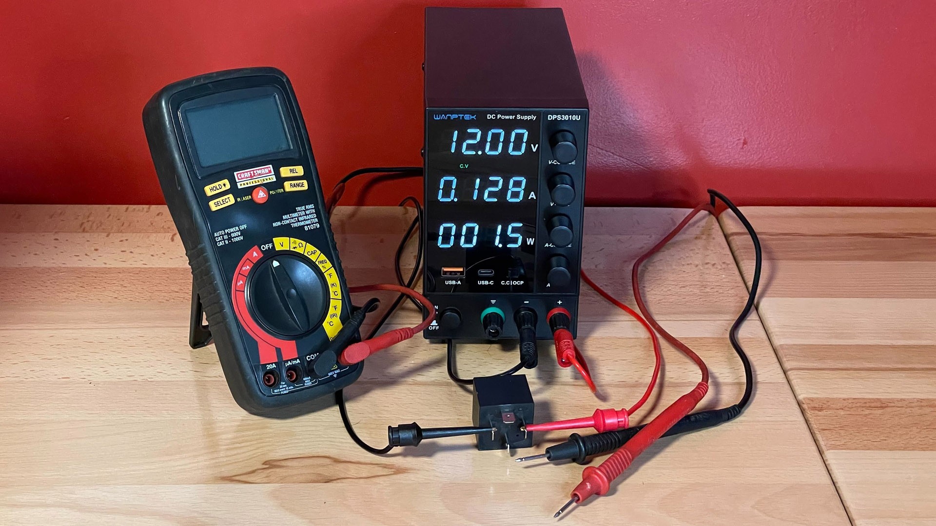
Testing a car relay is a straightforward process that doesn’t require a garage full of specialized equipment. You can perform effective tests with just a few basic tools. While you can test a relay directly in your car using the car’s battery, for more controlled and thorough testing, a benchtop setup is ideal.
Here’s what you’ll need:
Tools and Parts List:
- Multimeter: A digital multimeter is essential for measuring voltage, resistance (Ohms), and continuity.
- Power Supply (Benchtop Recommended): A benchtop power supply provides a stable and adjustable voltage source for testing relays outside of the car. Alternatively, you can use your car battery in a pinch.
- Jumper Wires (with alligator clips): For connecting the relay to the power supply and multimeter.
- Relay Tester (Optional but Recommended): For a more streamlined and user-friendly testing process, consider a dedicated relay tester. These devices often simplify the process and provide clear pass/fail indicators.
Step-by-Step Guide: How to Test a Car Relay
Let’s get into the step-by-step process of testing a car relay. Follow these instructions carefully for accurate diagnosis.
Step 1: Understanding Relay Functionality
Before you start testing, it’s important to understand how a relay works. In this guide, we’ll focus on the common four-pin Single-Pole Single-Throw (SPST) normally open relay, which is frequently used in automotive applications.
These relays typically have four pins, identified by the numbers 85, 86, 87, and 30. Pins 85 and 86 are for the relay coil circuit, which is the electromagnet that controls the switch. Pins 87 and 30 are part of the switched circuit, the power path that the relay controls.
When you apply power to the coil circuit (pins 85 and 86), the electromagnet is energized. This magnetic field pulls a small internal switch closed, creating a connection between pins 87 and 30. This allows current to flow through the switched circuit, powering the component connected to it – like headlights, fuel pump, or a cooling fan. When power is removed from the coil, the switch opens, interrupting the circuit.
The DIN 72552 standard provides a standardized pin designation for automotive relays:
- 30: Battery positive (+) supply to the relay.
- 85: Relay coil ground (-) connection.
- 86: Relay coil positive (+) connection.
- 87: Common output contact – Normally Open (NO).
- 87a: Normally Closed (NC) contact (not present on standard 4-pin relays).
- 87b: Normally Open (NO) contact (sometimes used in 5-pin relays).
Understanding this basic operation is key to effectively testing a relay.
Step 2: Locating the Relay in Your Vehicle
The first practical step is to find the relay you suspect is faulty. Relays are often located in fuse boxes under the hood or dashboard. Their exact location varies depending on the car’s make, model, and the system it controls.
- Consult your car’s repair manual: This is the most reliable way to locate specific relays. Look for fuse box diagrams or wiring diagrams that identify relay locations.
- Check fuse box labels: Fuse box covers often have diagrams or labels that indicate the function of each fuse and relay.
- Listen for the click: If you suspect a relay is failing, try to listen for a “clicking” sound when the system it controls is activated (e.g., turning on headlights). The click can help you pinpoint the general location of the relay.
Step 3: The Swap Test (Quick Check)
The simplest initial test is the swap test. If you have an identical, known-good relay, you can temporarily swap it with the suspect relay. Relays for non-essential systems (like windshield wipers or horn, if easily accessible) can be used for this test.
- Carefully remove the suspect relay: Gently pull the relay straight up from its socket.
- Install the known-good relay: Plug the replacement relay into the socket, ensuring it’s fully seated.
- Test the circuit: Activate the system controlled by the relay. If the problem is resolved, the original relay is likely faulty.
Caution: While quick, the swap test isn’t foolproof. If the underlying issue that caused the first relay to fail persists, it could damage the replacement relay as well. Further testing is recommended to confirm the relay failure and identify any root causes.
Step 4: Resistance Test (Coil Circuit)
Now, let’s move on to testing the relay with a multimeter. First, we’ll test the resistance of the relay coil.
- Set your multimeter to Ohms (Ω): Select the resistance setting on your multimeter.
- Identify coil pins: Locate pins 85 and 86 on the relay. These are the coil pins.
- Measure resistance: Place the multimeter probes on pins 85 and 86.
- Interpret the reading: A healthy relay coil should show a resistance reading between 50 and 120 Ohms. This range can vary slightly depending on the relay type, but a reading within this ballpark generally indicates a good coil.
- Very high or infinite resistance: Indicates an open coil, meaning the coil winding is broken. The relay is faulty.
- Very low resistance (close to 0 Ohms): Suggests a shorted coil, which is also a failure. The relay needs replacement.
Step 5: Continuity Test (Switch Circuit – Normally Open)
Next, we’ll test the continuity of the switch circuit in its normally open state.
- Keep multimeter in Ohms (Ω) mode: Or you can switch to continuity test mode if your multimeter has one (it usually beeps for continuity).
- Identify switch pins: Locate pins 87 and 30. These are the switch pins on a typical 4-pin relay.
- Measure resistance/continuity: Place the multimeter probes on pins 87 and 30.
- Interpret the reading: In a normally open relay, there should be no continuity between pins 87 and 30 when the relay is not energized.
- Infinite resistance (or no beep in continuity mode): This is the expected reading for a good relay. The switch is open.
- Low resistance or continuity (beep): Indicates that the switch is stuck closed. The relay is faulty and needs to be replaced.
Step 6: Energized Relay Test (Continuity)
This step verifies that the relay switch closes correctly when power is applied to the coil.
- Apply power to coil pins: Connect jumper wires from your power supply (or car battery) to pins 85 and 86. Pin 86 is typically positive, and pin 85 is negative, but check your relay diagram if unsure. Apply the rated voltage of the relay (usually 12V for automotive relays).
- Listen for the click: When you apply power, you should hear a distinct “click” sound from the relay. This indicates the electromagnet is working and the switch is attempting to close.
- Set multimeter to Continuity mode: If you switched to Ohms mode earlier, now switch to continuity test mode (beep symbol).
- Test switch pin continuity (energized): With power still applied to the coil, place the multimeter probes on pins 87 and 30.
- Interpret the reading:
- Beep (continuity): This is the expected result. It indicates that the switch is closing properly when the coil is energized, and current can flow through the switched circuit.
- No beep (no continuity): Indicates that the switch is not closing, even when the coil is energized. The relay is faulty.
Step 7: Voltage Drop Test (Switch Circuit – Energized)
Even if a relay switches and shows continuity, there could be internal contact resistance that reduces the voltage output. This step checks for excessive voltage drop across the relay contacts.
- Set multimeter to DC Volts mode: Select the DC voltage measurement setting on your multimeter.
- Measure input voltage: Connect the positive probe of your multimeter to pin 30 (power input to the switch) and the negative probe to ground (power supply negative terminal). Read and note the input voltage. This is your source voltage.
- Measure output voltage: Move the positive probe to pin 87 (power output from the switch). Keep the negative probe on ground. Read the voltage at pin 87.
- Compare readings: Ideally, the voltage at pin 87 should be very close to the input voltage at pin 30. A small voltage drop (e.g., 0.1-0.3V) is normal.
- Interpret the result:
- Voltage at pin 87 close to input voltage: The relay is passing voltage effectively.
- Significant voltage drop (e.g., >0.5V or more): Indicates excessive resistance within the relay contacts. This can reduce the power available to the component being powered and cause malfunctions. The relay should be replaced.
Congratulations! You’ve Tested Your Car Relay
By following these steps, you’ve thoroughly tested your car relay and can confidently determine if it’s functioning correctly. If your relay fails any of these tests, it’s time to replace it with a new one. Relays are relatively inexpensive and readily available at auto parts stores.
Video Resource: Visual Guide to Relay Testing
Sometimes seeing a process demonstrated visually can be incredibly helpful. If you’re new to relay testing, this video provides a clear visual guide to reinforce the steps we’ve covered.
Equip Yourself for Success
Having the right tools makes any DIY car repair task easier and more efficient. Investing in quality tools and understanding basic diagnostic procedures, like how to test a car relay, empowers you to maintain your vehicle and address common electrical issues yourself. Explore our guides and gear recommendations to equip your garage for automotive success.
DISCOVER MORE DIY RESOURCES