Is your car’s air conditioning not blowing as cold as it used to? If your vehicle is over 6-8 years old, a likely culprit is low refrigerant. Many car owners experience a gradual decrease in AC cooling performance over time, often accompanied by tell-tale signs like weak airflow and even a faint hissing sound from the vents. The good news is that recharging your car AC, or adding refrigerant, can be a straightforward DIY task, potentially saving you a trip to the mechanic and restoring that refreshing cool air you crave on hot days.
This guide, inspired by a hands-on experience from a fellow car enthusiast, will walk you through the process of how to Recharge Car Ac refrigerant at home. We’ll cover everything from diagnosing the issue and gathering the necessary tools to safely and effectively topping up your system. While this DIY approach is rewarding and educational, it’s important to emphasize that safety and accuracy are paramount when dealing with automotive AC systems.
Before we dive in, it’s crucial to understand that this guide is for informational purposes and based on personal experience. If you’re uncomfortable working on your car’s AC system or suspect a more serious issue, consulting a certified HVAC technician is always recommended.
Diagnosing Low Refrigerant: Is it Time to Recharge Your Car AC?
Before you jump into recharging your car AC, it’s wise to rule out other potential problems. A systematic check of your AC system components can help pinpoint the issue and ensure that low refrigerant is indeed the cause of your cooling woes. Here’s a basic troubleshooting checklist:
- Compressor: When you turn on your AC, listen for a distinct “click” sound, indicating the compressor engaging. Visually inspect the compressor drive belt for any signs of damage or looseness. A faulty compressor clutch or a worn belt can prevent the AC system from functioning correctly.
- Evaporator: A properly functioning evaporator shouldn’t have any leaks. Check your car’s footwells for any unusual water accumulation, which could indicate a clogged evaporator drain. While less common to visually inspect, if you can access the cabin air filter cavity, check for excessive frosting, which might suggest evaporator issues.
- Condenser: The condenser, located in front of the radiator, dissipates heat from the refrigerant. Examine the condenser fins for blockage from debris, insects, or dirt. Gentle cleaning with compressed air can improve airflow and condenser efficiency. Avoid using harsh alkali cleaners, which can damage the delicate fins.
- Expansion Valve: This valve regulates refrigerant flow into the evaporator. While diagnosing a faulty expansion valve without specialized equipment can be tricky, it’s less frequently the cause of reduced cooling compared to low refrigerant.
- Blower Motor and Resistor: Ensure your blower fan operates at different speeds. If it’s stuck on one speed, the blower motor resistor might be faulty. A malfunctioning blower will limit airflow and cooling effectiveness regardless of refrigerant levels.
- Cabin Air Filter: A clogged cabin air filter restricts airflow into the cabin, reducing AC performance. Regularly replacing your cabin air filter (typically every 12,000 to 15,000 miles or annually) is good maintenance practice.
If all these components appear to be functioning correctly, the most likely culprit for reduced AC cooling, especially in older vehicles, is low refrigerant.
Why Does Refrigerant Leak?
Car AC systems are designed to be sealed, but refrigerant loss over time is a common occurrence. Here’s why:
- Permeation through Rubber Components: Flexible rubber hoses and O-ring seals are used throughout the AC system. Over years of thermal cycling and exposure to engine bay heat, these rubber components can become slightly porous, allowing minute amounts of refrigerant to escape (permeation).
- Minor Leaks at Connections: Even with tight fittings, microscopic leaks can develop at connection points between hoses, pipes, and components, especially as seals age and harden.
- Schrader Valves: These valves, similar to tire valves, are used for servicing the AC system. While designed to seal, extremely minor leaks can sometimes occur from these valves over extended periods.
- Damage to Components: Road debris, particularly stones hitting the condenser coil, can cause punctures and refrigerant leaks. Corrosion in metal lines or condenser/evaporator coils can also lead to leaks over time.
If your car is 6-8 years old or more and you’ve never had your AC system recharged, low refrigerant is a highly probable cause of diminished cooling. In such cases, recharging the system can often restore its cooling efficiency, provided there are no significant leaks.
Tools and Materials for Recharging Your Car AC
To safely and effectively recharge your car AC, you’ll need the following tools and consumables. Investing in quality tools will make the process smoother and safer.
Essential Tools
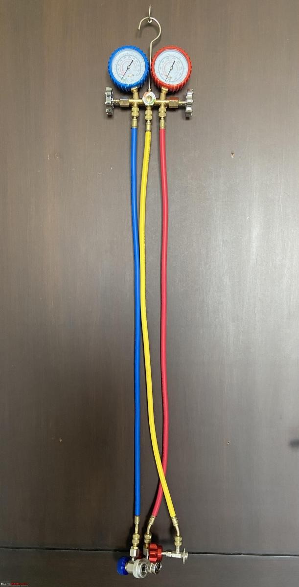
- AC Manifold Gauge Set: This is the core tool for AC work. It consists of:
- Manifold Body: Typically made of brass, it houses pressure gauges and control valves.
- Low-Pressure Gauge (Blue): Measures pressure on the low side of the system (0-220 psi range).
- High-Pressure Gauge (Red): Measures pressure on the high side (0-500 psi range).
- Control Valves: Knobs to control refrigerant flow.
- Gauge Glass (Sight Glass): A window in the manifold to observe refrigerant flow during charging.
- Hoses (Color-Coded):
- Blue Hose: Connects to the low-pressure (LP) port.
- Red Hose: Connects to the high-pressure (HP) port.
- Yellow Hose: Service hose, connects to the refrigerant source (can) or vacuum pump.
- Quick Couplers (Color-Coded & Size-Specific):
- Blue Quick Coupler (LP): Smaller opening, fits only the low-pressure port.
- Red Quick Coupler (HP): Larger opening, fits only the high-pressure port. These prevent accidental connection to the wrong port.
- Refrigerant Can Tap Valve: Attaches to the refrigerant can to pierce and control refrigerant flow.
- Probe Thermometer (or Digital Multimeter with Thermocouple): To measure vent air temperature and assess cooling performance.
 AC Manifold Gauge Set
Image of a probe thermometer, used to measure the temperature of air coming from the car’s vents.
Consumables and PPE
- R-134a Refrigerant Can: The specific type and quantity of refrigerant your car uses will be indicated on a sticker in the engine bay or under the hood. R-134a is a common type for older vehicles. A 12-14 ounce can (approximately 340-400 grams) is often sufficient for topping up a system. Always verify the correct refrigerant type for your vehicle.
- Safety Goggles: Protect your eyes from refrigerant splashes, which can cause frostbite.
- Nitrile Gloves: Protect your skin from direct contact with refrigerant, which can also cause frostbite.
Image of a can of R-134a refrigerant, a common type used in car AC systems.
Image of a vehicle AC refrigerant sticker, indicating the type and amount of refrigerant the system uses.
Understanding the AC Manifold Gauge Set
The AC manifold gauge set is the central tool for diagnosing and servicing your car’s AC system. Let’s break down its components:
Pressure Gauges
- Low-Pressure Gauge (Blue): Indicates the pressure on the suction side of the compressor. During normal operation, this reading is typically lower.
- High-Pressure Gauge (Red): Indicates the pressure on the discharge side of the compressor. This reading is usually higher than the low-pressure side.
These gauges provide vital information about the refrigerant pressures within the system, helping you determine if the system is properly charged and functioning correctly.
Image highlighting the pressure gauges on an AC manifold set, showing the low-pressure (blue) and high-pressure (red) gauges.
Manifold Body and Valves
The manifold body connects the gauges, hoses, and control valves. Valves on either side of the manifold (typically blue for LP and red for HP) control the flow of refrigerant. During recharging, the low-pressure side valve is opened to allow refrigerant to flow into the system.
Image close-up of the gauge glass (sight glass) on an AC manifold, used to visually monitor refrigerant flow.
Color-Coded Hoses and Quick Couplers
- Color Coding: Blue for low pressure, red for high pressure, and yellow for service (charging/evacuating) ensures correct connections and reduces the risk of errors.
- Quick Couplers: These fittings snap onto the car’s service ports for quick and secure connections. They are size-specific to prevent accidental connection to the wrong port.
Image showing the color-coded hoses of an AC manifold set: blue (low pressure), red (high pressure), and yellow (service).
Image of a Schrader valve fitting at the end of an AC hose.
Image of quick coupler fittings for an AC manifold set, highlighting the color coding and different sizes for LP and HP ports.
Image emphasizing the size difference between the low-pressure (smaller opening) and high-pressure (larger opening) quick couplers, preventing misconnections.
Image demonstrating how a quick coupler connects to a car’s AC service port, similar to a gas cylinder regulator.
Refrigerant Can Tap Valve
This valve is designed to safely pierce the refrigerant can and provide a controlled connection to the yellow service hose. Crucially, ensure the valve is open (needle retracted) before screwing it onto the can to prevent accidental piercing and refrigerant release.
Image of a refrigerant can tap valve with a pointy end for piercing the can, used to connect the refrigerant can to the AC manifold.
Vacuum Pump/Recovery Unit (For System Evacuation – Not for Basic Recharge)
While not needed for a simple recharge, understanding the yellow hose’s purpose in evacuation is helpful. For more extensive AC work like component replacement, the yellow hose connects to a vacuum pump (to remove air and moisture before charging) or a refrigerant recovery unit (to safely remove refrigerant from the system).
(Source: Google Images) Image of an AC vacuum pump, used for evacuating air and moisture from the AC system before charging.
Hose Parking Ports
Many manifold sets include dummy ports on the back to store hoses when not in use, keeping them clean and preventing debris from entering.
Image showing dummy threaded ports on the back of an AC manifold set, used for parking and storing hoses when not in use.
Image demonstrating hoses parked in the dummy ports on the back of an AC manifold set, for clean and organized storage.
Step-by-Step Procedure to Recharge Your Car AC
Now that you have your tools and understand the components, let’s proceed with the recharge car AC procedure. Always work in a well-ventilated area and wear safety goggles and gloves.
- Initial Vent Temperature Measurement: Start your car’s engine, set the AC to the coldest setting, blower fan on high, and close all windows. Use your probe thermometer to measure the air temperature coming from the center vents. Note this reading as your baseline.
Image showing a probe thermometer inserted into a car’s AC vent to measure the initial air temperature.
Image of a digital multimeter displaying the vent air temperature reading.
- Prepare the Manifold and Refrigerant Can: Open the hood of your car. Hang the AC manifold set by its hook in a convenient location. Ensure both manifold valves (LP and HP) are fully closed. Attach the refrigerant can tap valve to the refrigerant can, making sure the valve is in the open (retracted needle) position before screwing it onto the can.
Image showing the AC manifold gauge set hanging under the car’s hood, with the refrigerant can and tap valve prepared for connection.
-
Locate the AC Service Ports: Identify the low-pressure (LP) and high-pressure (HP) service ports in your car’s engine bay.
- Low-Pressure Port: Usually located on a larger diameter pipe, often near the accumulator or drier. It typically has a smaller diameter port fitting.
- High-Pressure Port: Usually located on a smaller diameter pipe, often closer to the condenser or compressor. It typically has a larger diameter port fitting.
Image showing the location of low-pressure (LP) and high-pressure (HP) AC service ports in a car’s engine bay.
- Remove Dust Caps and Connect Couplers: Remove the dust caps from both service ports and keep them in a safe place. Connect the blue quick coupler (LP) to the LP service port and the red quick coupler (HP) to the HP service port. Ensure the quick couplers are in the closed position when connecting.
Image of dust caps being removed from the car’s AC service ports, preparing for quick coupler connection.
Image showing the blue (LP) and red (HP) quick couplers connected to their respective service ports on the car.
- Open Quick Coupler Valves and Check Initial Pressure: Gently open the valves on both quick couplers. Pressure readings should now appear on the gauges, even with the manifold valves closed. This reading indicates the static pressure in the system.
Animated image showing the pressure gauges on the AC manifold registering readings after the quick couplers are connected to the service ports.
- Start Engine, Run AC, and Check Pressure Readings: Have an assistant start the engine and rev it to approximately 1500 RPM. Observe the pressure readings on both gauges with the AC running at maximum cooling.
Image showing the pressure gauges on the AC manifold with the engine running and AC system operating.
- Compare Readings to Pressure-Temperature Chart: Measure the ambient temperature around your car. Refer to an R-134a pressure-temperature chart (readily available online or often included with manifold sets). Compare your gauge readings to the chart values for your ambient temperature.
Image of a pressure-temperature chart for R-134a refrigerant, used to determine correct operating pressures based on ambient temperature.
*   **Typical Readings (at ~28°C/82°F Ambient):**
    *   **Low-Pressure (LP):** 25-45 psi
    *   **High-Pressure (HP):** 150-250 psi

Low HP readings often indicate low refrigerant.
Image showing gauge readings on the AC manifold indicating low high-side pressure, suggesting low refrigerant levels.
- Prepare to Charge (Safety First): Put on your safety goggles and nitrile gloves. Ensure the refrigerant can tap valve is still closed (needle retracted). Screw the valve clockwise to pierce the refrigerant can, then turn it counter-clockwise to open and allow refrigerant flow.
Image of a person wearing safety goggles and nitrile gloves, preparing to recharge the car AC system.
Image showing the refrigerant can tap valve piercing the refrigerant can, ready to dispense refrigerant into the system.
- Purge Air from Yellow Hose: Loosen the yellow hose connection at the manifold slightly to purge any air from the hose. Briefly allow refrigerant to escape until you hear a hissing sound, then retighten the connection. This removes air and moisture from the charging line.
Animated image demonstrating purging air from the yellow hose by briefly loosening the connection at the manifold.
- Begin Charging Refrigerant (Slowly): Gently and slowly open the low-pressure (LP) side manifold valve. Refrigerant will begin to flow into the system. Observe the gauge glass for refrigerant flow (liquid phase). Charge in short bursts, closing the valve intermittently.
Image showing the low-pressure (LP) manifold valve being opened to begin charging refrigerant into the car’s AC system.
Animated image illustrating refrigerant flow in liquid phase through the gauge glass (sight glass) of the AC manifold during charging.
- Monitor Pressure Gauges and Vent Temperature: Watch the high-pressure (HP) gauge as you add refrigerant. The HP reading should gradually increase. Refer to the pressure-temperature chart and aim for the correct HP reading for your ambient temperature. Periodically check the vent temperature with your thermometer.
Image showing the pressure gauges being monitored during the refrigerant charging process, with the high-pressure gauge needle gradually rising.
- Stop Charging at Correct Pressure: Once the HP gauge reading reaches the target range from the pressure-temperature chart, close the LP manifold valve completely. Do not overcharge the system. Overcharging can reduce cooling performance and potentially damage components.
Image of gauge readings on the AC manifold after successful refrigerant charging, showing pressures within the desired range.
- Final Vent Temperature Check: Re-measure the vent air temperature with your probe thermometer. It should now be significantly colder than your initial reading, indicating successful recharge car AC process.
Image of a digital multimeter displaying a lower vent air temperature reading after the AC system has been recharged.
- Disconnect and Store Equipment: Close the valves on the quick couplers. Carefully disconnect the quick couplers from the service ports. Replace the dust caps on the service ports. Remove the refrigerant can and tap valve. Store your AC manifold set and components properly.
Conclusion: Enjoy Restored Cooling
By following these steps, you can successfully recharge car AC refrigerant and restore cooling performance to your vehicle. This DIY approach can save you money and provide a valuable learning experience. However, remember that this guide is for basic top-up situations.
If you continue to experience AC issues, or if the system loses refrigerant quickly after recharging, it’s essential to consult a qualified car AC technician. They can diagnose potential leaks, compressor problems, or other complex issues that require professional expertise.
Disclaimer: This guide is based on personal experience and for informational purposes only. Automotive AC systems operate under high pressure and involve refrigerants that can be harmful if mishandled. If you are not comfortable with DIY automotive work, please seek professional assistance from a certified HVAC technician. Always prioritize safety and follow proper procedures when working on your car’s AC system.
For further learning, refer to resources like automotive AC training manuals and consult with experienced technicians if needed.